
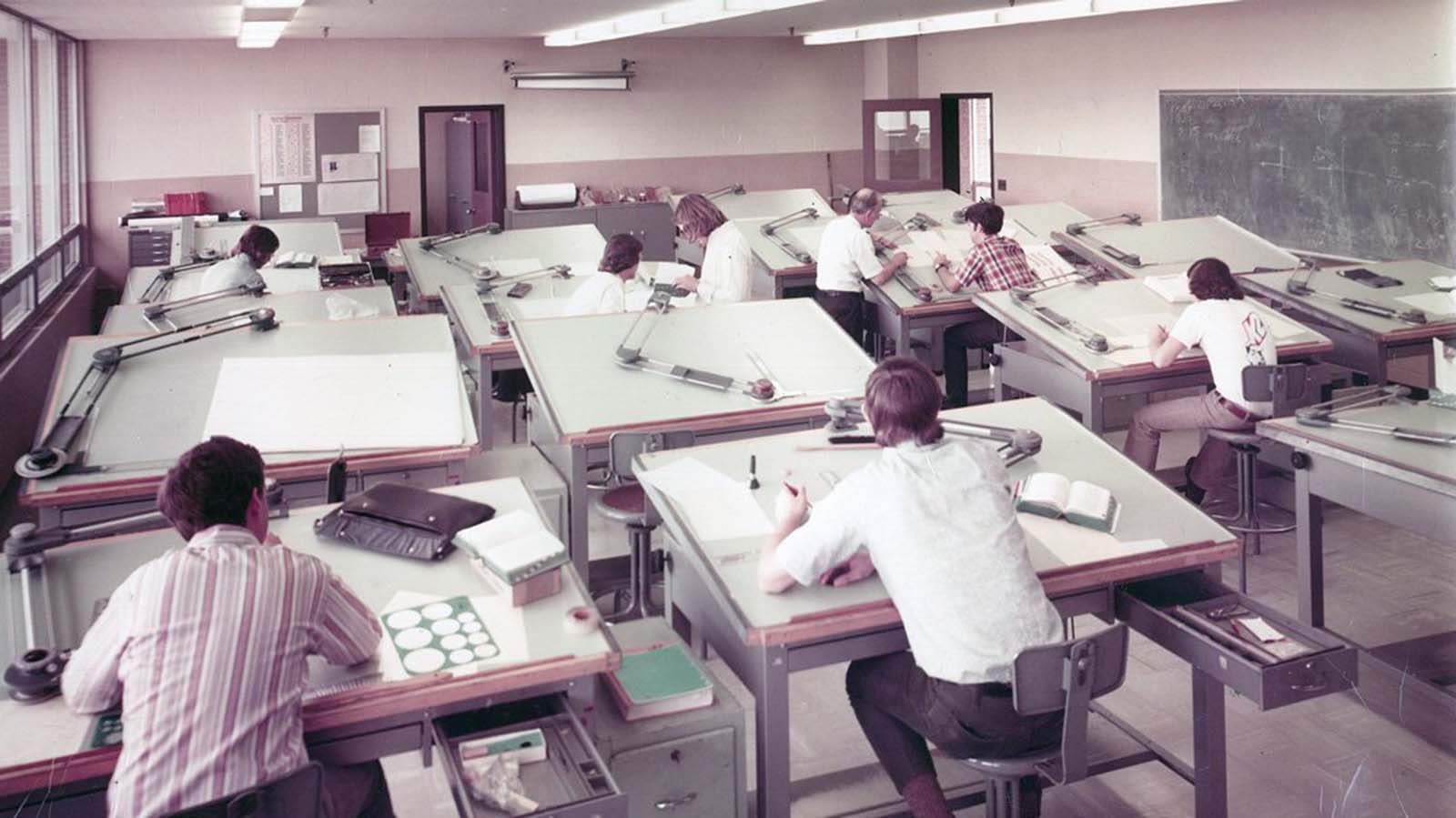
I recently began thinking about my early exposure to the architecture profession and how primitive those days seem now.
I began as a simple draftsman in 1961 (Wow! Has it really been over 60 years?) at $40 per week. I had left a job as a photoengraving cameraman at which I was making $60 per week but had decided that a career change was in order and I was tired of commuting to Lexington every day.
I had had only one drafting class in my first year of college (1959), so had very little experience when I was hired. In class, we had used the old T‑square, which was only useful on a relatively small board. In the job I graduated to, using the parallel bar was a vast improvement over the cumbersome T‑square. The parallel bar is held in a constant horizontal position by a single corded cable that is fed through the bar in both directions and then attached to the board at four corners. It’s a simple but ingenious method of allowing the bar to move and remain at the same angle at all times.


In those days, we produced “real” blueprints. They were copies of our drawings produced by a printing process that resulted in a print of white lettering and images on a dark blue background. When left in the sun for any length of time, they quickly faded to unreadability.
However, original drawings were made on high-quality paper or, on occasion, a linen material that was much more permanent (and much more expensive) but required inked images. Using ink for drawing required a ruling pen and a deft hand to prevent ink “splotches” when too much ink escaped from the nib, which occasionally ran under the parallel bar to be spread around on the drawing. Repairs were time-consuming.
Combined with the parallel bar were triangles of varying sizes, usually 45 degrees or 30–60 degrees, as well as adjustable triangles. By combining these instruments, one could easily draw horizontal, vertical, and diagonal lines.

We also supplied ourselves with numerous templates, circles, ovals, squares, and plumbing fixtures. The latter were usually available free from the fixture manufacturers. For curved surfaces, we utilized French curves or a compass to draw very large circles. Many student compasses came with an arm extension that, when attached to the base instrument, made it into a “beam compass.” Most of these were designed to be fitted with either a drawing lead or a pen nib for ink work.
Never miss a thing with our FREE weekly newsletter.
Drafting rooms were usually equipped with drawing boards somewhat higher than a standard desk, and stools were typical. Eventually, lower desks and drawing boards became standard, but the higher boards allowed one to either sit or stand — and standing was sometimes more convenient when having to reach the upper limits of the drawing.
It was not uncommon for draftsmen (there were very few women in the profession at the time) to wear an apron while working because the graphite from the drawing would often find its way onto one’s shirt. When we wore ties to work, which was usual, we tucked them into our shirts to keep them clean.
Drafting pencils (lead holders) held a piece of lead about four inches long, which was periodically extended by pressing on the back end of the holder. Leads came in several degrees of hardness, from 4H (quite hard) to HB (very soft). They were sharpened on a small sandpaper pad or, if one was fortunate enough, a manual sharpener. It’s probably hard to see in the photo, but one side of the sharpener’s “spout” has been worn away by constant use. The lead holder was inserted into the sharpener and then used to rotate the top. The lead within was sharpened on a grit inside the sharpener, and the graphite left in the container had to be periodically emptied. Woe unto him who spilled the container!

It was frequently necessary to total distances, which often entailed using fractions of an inch (I still believe that the metric system would have greatly simplified our work). The simple calculator of the day was an instrument called an Addometer. This was a metal box containing several geared wheels which, when turned in sequence, would add — and subtract — multiples of feet, inches, and fractions of an inch (down to 1/8ths). The wheels were turned by inserting a small metal stylus into the appropriate hole and rotating it like a telephone dial. Once 7/8ths of an inch was reached, the next turn would turn the adjacent wheel to note an inch, and so on to feet and multiples of feet. Distances could be subtracted by rotating the wheels in the opposing direction. The device was cleared by pulling the slide at the lower right-hand corner, returning all the wheels to zero.

Today’s computer drafting is a far cry from the practice of 60 years ago and has dramatically simplified the tasks of the draftsperson and architect. Still, some of the romance and “hands-on” experience has been eliminated. There is good and bad in all technological advancements.
